- Expertise
- Our Work
- SBIR / STTR
- Request A Quote
- Contact
(610) 964-9000


Who We Are

As a small business with a staff of highly skilled, multi-faceted engineers, MR&D is uniquely positioned for lean, responsive analysis and design work to support your company and your customers’ needs. Our extensive experience, in-house material databases and proprietary analysis tools enable accurate, innovative solutions for the advanced material systems of the future. At a time when next-generation materials are ever more costly to manufacture, while lead times and budgets are shrinking, MR&D will ensure your project is completed on time and within budget.
What We Do
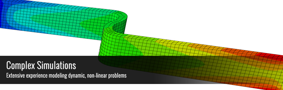
MR&D has capabilities in wide range of composite design & analysis and component manufacturing projects including material design, component design and analysis, test design, planning, on-site support, post-test data correlation, and parts manufacture.
About

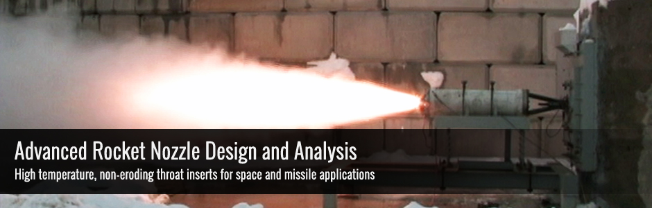
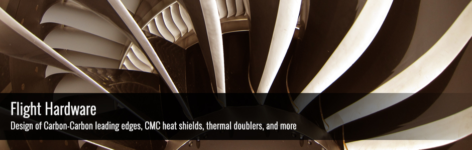
MR&D was founded in 1996 by Dr. Brian Sullivan and Kent Buesking to provide research, analysis and design services to the advanced materials community, focusing on composite materials for the aerospace industry. Our work encompasses all types of materials, including carbon-carbon, ceramic matrix composites (CMC), oxides, and refractory metals.